






If you are designing an electric vehicle, off-highway machine or stationary power system, removing heat is only part of the challenge. The harder question is how to move that heat through the application reliably and efficiently under every expected operating condition.
That is where liquid cooling becomes valuable.
By circulating coolant between heat-generating components and a heat exchanger, a liquid-cooling circuit provides a controlled route for thermal energy. It can collect heat from batteries, power electronics, fuel cells or combustion engines, carry it away from confined areas and reject it where suitable airflow is available.
The principle is straightforward. Designing a circuit that performs consistently is not.
Flow rate, pressure drop, coolant properties, heat exchanger capacity, ambient temperature and control strategy all affect the result. A high-flow pump or larger cooler will not compensate for a circuit designed as separate components rather than a complete system.
In this article, we will explain how liquid cooling works, where it is used and what engineers need to consider when designing an effective liquid thermal-management system.
What is Liquid Cooling?
Liquid cooling uses a circulating fluid to absorb heat from one part of an application and carry it elsewhere for rejection or reuse.
Coolant flows through dedicated cooling channels within or in contact with the component requiring temperature control, absorbing heat as it circulates. Heat transfers into the fluid before an electric water pump circulates it towards a heat exchanger. The coolant releases the collected heat and returns to repeat the process.
At a high level, the circuit has four stages:
- Heat absorption: Energy moves from the component into the coolant.
- Coolant circulation: A pump moves the heated fluid through the circuit.
- Heat rejection or transfer: A heat exchanger releases the energy to ambient air, refrigerant or another coolant loop.
- Coolant return: The fluid returns to the heat source.
The hardware changes, but the purpose remains the same: provide a predictable path for heat to move from where it is generated to where it can be managed or rejected.
What Makes Up a Liquid-Cooling Circuit?
A liquid-cooling system is not one cooling component. It is a circuit whose performance depends on every element working at the required operating point.
The main elements typically include:
- Coolant to absorb and transport thermal energy
- A water pump to create flow and overcome circuit resistance
- A heat exchanger to release heat to air, refrigerant or another fluid loop
- Fans and airflow paths for liquid-to-air heat rejection
Some systems also connect the coolant loop to an electric water heater, chiller or reversible heat pump. This allows the circuit to provide heating as well as cooling, or to reduce coolant temperature below what ambient heat rejection can achieve.
That distinction is important: liquid cooling describes how heat is transported around the application, not necessarily how it is ultimately rejected.
Why Use Liquid Cooling Instead of Air Cooling?
Air cooling transfers heat directly from a component into an airflow. It can be simple, lightweight and effective when heat loads are modest and sufficient airflow is available.
Liquid cooling adds pumps, pipework, coolant and additional components, but it allows heat to be collected from a single, confined component and carried to a more suitable rejection point. This becomes increasingly useful as power density rises and packaging becomes tighter.

Differences in Air Cooling and Liquid Cooling
| Design consideration | Air Cooling | Liquid Cooling |
|---|---|---|
|
Heat transport |
Heat transfers directly to local airflow |
Heat can be transported elsewhere |
|
Packaging |
Requires airflow at the component |
Allows remote heat-exchanger positioning |
|
Complexity |
Generally fewer components |
Requires fluid management and additional hardware |
|
Temperature control |
Can be affected by uneven airflow |
Can provide more controlled distribution |
|
Best suited to |
Moderate loads with suitable airflow |
Higher heat density or confined installations |
Neither method is automatically better. Selection depends on heat load, target temperature, ambient conditions, duty cycle, packaging, airflow and acceptable auxiliary power.
For a wider comparison, read this article we produced: Active vs Passive Cooling in Heavy Vehicles and Stationary Power Applications
Where is Liquid Cooling Used?
Liquid cooling supports combustion, electrified and stationary power applications, but each places different demands on the circuit.
The demands vary considerably.
Electric Buses
An electric bus needs to manage battery temperature during driving and charging, alongside heat from motors and power electronics.
Off Highway Vehicles
An off-highway machine may face sustained heavy loads, restricted airflow and challenging ambient conditions.
Stationary Power
Stationary power systems need to manage heat during prolonged operation
Data Centres
Data Centres must remove concentrated heat from equipment operating continuously.
These differences influence how the circuit is designed, where heat is rejected and how cooling is controlled. The principle remains the same, but the solution must reflect the application’s temperatures, duty cycle and available space.
What Factors Affect Liquid Cooling Performance?
The effectiveness of a liquid-cooling system depends on several factors working together, rather than any single component. Heat load, operating temperatures, coolant flow, fluid properties and system control all influence how reliably and efficiently heat can be managed.
Heat Load, Temperature And Ambient Conditions
The first question is how much heat the system must manage during continuous operation and peak loads.
Target component and coolant temperatures are equally important. A circuit rejecting heat to ambient air needs a sufficient temperature difference between the coolant and the air. As ambient temperature approaches the coolant target, heat rejection becomes more difficult and the required heat exchanger or airflow increases.
If coolant must remain below ambient temperature, a liquid-to-air cooler alone cannot achieve it. The circuit will need an active cooling stage such as a refrigerant chiller.
Coolant Flow And Pressure Drop
Flow rate describes how much coolant moves through the circuit, but a pump can only deliver that flow against the resistance of the installed system.
Every hose, bend, manifold, valve, cold plate and heat exchanger introduces pressure drop. As circuit resistance increases, the flow available from the pump reduces. This is why a maximum free-flow figure does not describe installed performance.
Increasing flow can improve heat transfer, but the benefit reduces as flow rises while pressure loss and pump power increase. The objective is not maximum flow. It is the flow distribution required to control temperature at an acceptable energy demand.
Read our Pressure, Flow Rate and Electric Water Pumps article for a deeper explanation.
Coolant Properties
Water has favourable heat-transfer properties, but pure water is unsuitable for many vehicle and industrial circuits because freeze protection, boiling margin, corrosion control and material compatibility must also be considered.
Water-glycol mixtures are widely used. Glycol provides freeze protection but also changes viscosity, specific heat capacity and thermal conductivity. Concentration consequently affects both heat transfer and the pressure required to circulate the fluid, particularly at low temperatures.
Coolant selection should reflect the operating temperature range, materials, corrosion protection, electrical requirements, viscosity and service life. Pumps and heat exchangers should be assessed using the intended fluid rather than an assumed water-only condition.
Control Strategy
A cooling system may be sized for peak conditions, but it rarely needs maximum pump and fan output continuously.
In a multi-loop system, control may need to balance component protection, battery conditioning, cabin comfort, energy use and warm-up time simultaneously. A change in one circuit can alter conditions elsewhere, making system-level control essential.
In summary:
- Cooling performance depends on heat load, target temperature and ambient conditions.
- Required flow must be delivered against the pressure drop of the installed circuit.
- Heat exchanger capacity is only useful when sufficient airflow is available.
- Coolant choice changes thermal and hydraulic behaviour.
- Pumps, fans and valves must operate as one coordinated system.
Is Liquid Cooling Passive or Active?
The distinction depends on how the system rejects heat.
A liquid circuit connected to an ambient cooler can provide passive heat rejection when surrounding air is cool enough to absorb heat from the coolant. Pumps and fans still consume power, but no refrigeration cycle is used to lower coolant temperature below ambient.
When ambient heat rejection is insufficient, coolant can pass through a refrigerant chiller. The refrigeration circuit actively transfers heat and can maintain a coolant target below ambient temperature.
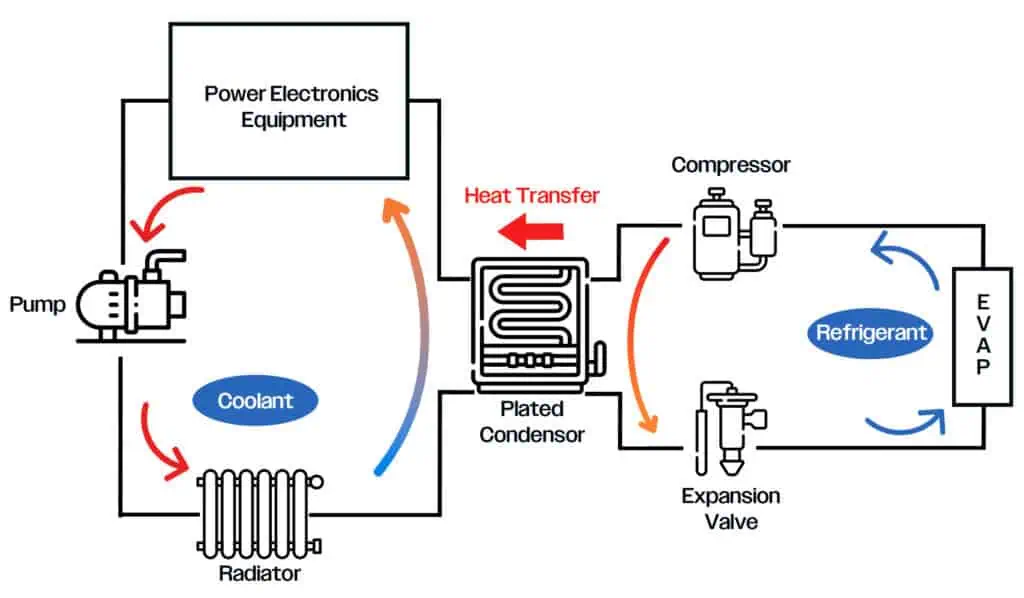
Where refrigerant transfers heat into coolant loops, the condensing strategy affects packaging and system flexibility. Understanding Condensing in Thermal Systems: Direct vs Indirect Approaches explains this relationship in more detail.
Cooling Capacity is Not The Only Measure of Efficiency
Pumps consume energy to overcome hydraulic resistance, fans consume energy to move air, and compressors add further demand when active cooling is required. These loads can affect fuel consumption, battery range or useful stationary power output.
System efficiency can be improved by reducing unnecessary circuit resistance, providing a low-restriction airflow path and matching pump, fan and compressor output to actual thermal demand. Passive heat rejection and heat recovery should also be used where conditions allow.
The aim is not the lowest possible pump or fan speed. It is the lowest practical energy use that keeps every component within its required temperature limits.
Is Liquid Cooling Always the Right Approach?
Liquid cooling offers strong heat-transport capability, but it also introduces weight, fluid connections, leak risk, filling requirements and control complexity.
Before selecting it, engineers should define:
- Continuous and peak heat loads
- Target component and coolant temperatures
- Minimum and maximum ambient conditions
- Duty cycle and available airflow
- Packaging, mass and auxiliary-power limits
- Heating, pre-conditioning or heat-recovery requirements
- Maintenance, service access and failure response
For a lower heat load with good airflow, direct air cooling may be sufficient.
Other high-density applications may require refrigerant cooling, immersion cooling or a specialist architecture. Defining the requirement first makes it easier to select the correct technology rather than designing the application around a preferred solution.
From Liquid Cooling to Complete Thermal Management
Modern electrified platforms may need to manage batteries, power electronics, motors, fuel cells and cabin Heating, Ventilation and Air Conditioning (HVAC) simultaneously. Treating each requirement independently can create multiple pumps, fans, heat exchangers and controls competing for space and energy.
A systems-level approach instead considers where heat is generated, where it needs to go and whether it can be reused. Under suitable conditions, heat from power electronics or another coolant loop may support battery conditioning or cabin heating, while cooling capacity can be shared between operating modes.
This is the principle behind a Complete Thermal Management System (CTMS): liquid circuits, refrigerant functions, airflow and controls are treated as one coordinated architecture. The objective is not simply to reject heat, but to move, reuse and control it according to the needs of the complete application.
Our Rethinking Thermal Management with the CM-Series CTMS: From Components to Systems article shows how this approach behaves under real operating conditions.
The Complete Circuit Determines the Result
Liquid cooling is valuable where heat loads are concentrated, airflow is difficult to provide or temperature distribution must be closely controlled.
Its effectiveness does not come from the coolant alone. It comes from matching the heat source, coolant, pump, circuit resistance, heat exchanger, airflow and controls across the full operating range.
Good liquid-cooling design therefore starts with the application rather than an individual component. When the complete thermal path is understood early, engineers can make better decisions about architecture, component sizing, control and energy use before packaging constraints make those decisions harder.

Grayson’s CM-Series CTMS uses indirect condensing to manage heat across several vehicle systems, including battery coolant, power electronics coolant and cabin HVAC system.
The CTMS calculates the most efficient way to transfer heat to manage all thermal requirements of the vehicle. It will transfer heat into the power electronics coolant (indirect condensing) and reject it to atmosphere through the coolant radiator. Alternatively, it will extract heat from the power electronics coolant through the process of heat recovery or air source heat scavenging. This process enables the compact system to reduce the amount of refrigerant used, making it ideal for modern electric and hybrid vehicles.
If you are defining a liquid-cooling circuit or reviewing a wider thermal architecture, Grayson’s engineering team can support system selection, integration and validation around the requirements of your application.
Get in touch: https://www.graysonts.com/contact/
Related Articles


